V Mount IC/Radiator Installation Guide

|
V Mount IC/Radiator Installation Guide |
|
Thank you for purchasing Rotary Extreme V mount IC/Rad. With proper installation, you will find this setup to be the best on the market in terms of intake temperature and water temperature control. Please read the installation instruction carefully before you attempt the installation.
Tools: metric socket set, metric wrench set, drill and drill bits set (at least 1/4" and 3/16"), Dremel with cutting wheel, Philips screw driver, flathead screw driver, crimping tool, utility knife, pipe bender, safety goggle, 3M N95 dust mask, latex gloves
Other items you need: 12 gauge wires in 4 different colors, each color wire for at least 5 ft. long. 16 butt connectors for 12 gauge wires, wire loom, electric tape, zip ties. You might need some coolant hoses and clamps if you plan to keep the AST.
Installation:
1. Remove the following items from the engine bay in the following order: intake box, battery, battery tray, intercooler, stock elbow, intercooler duct, A/C dryer, radiator, underpanel, front bumper, A/C condenser and A/C condenser brackets. Unbolt the front two power steering line brackets. Please refer to the Mazda shop manual for detail instruction.
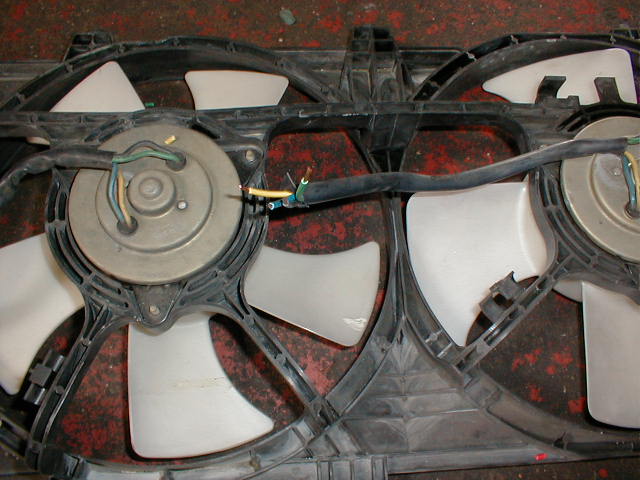
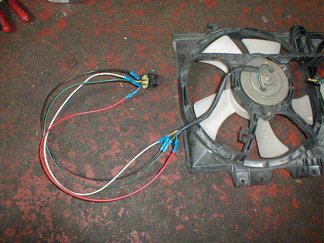
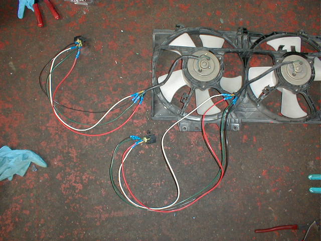
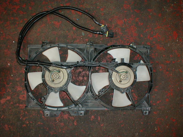
2. Extend the Fan Wires: One side should be extended by 2 ft. and the other should be extend by 3 ft. Use the 12 gauge wires and butt connector for extension. Put the wires in the wire loom and wrap it with electric tape. Zip tie the wire looms onto the fan shroud and make sure they will clear the fan blades. Mount the fan assembly onto the V mount radiator.
 |
 |
 |
 |
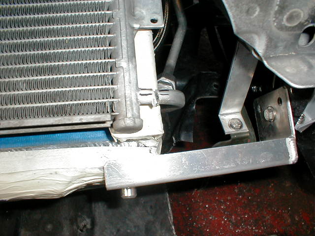
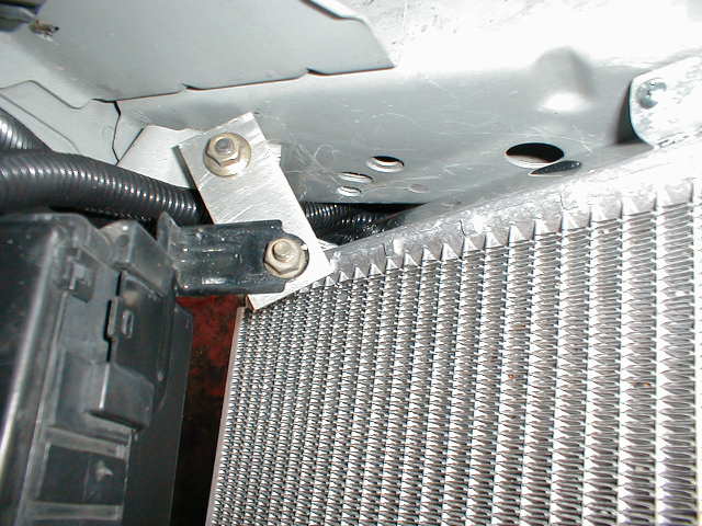
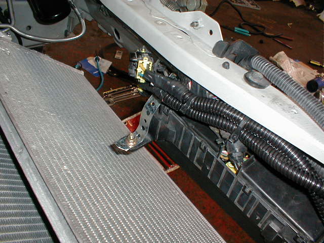
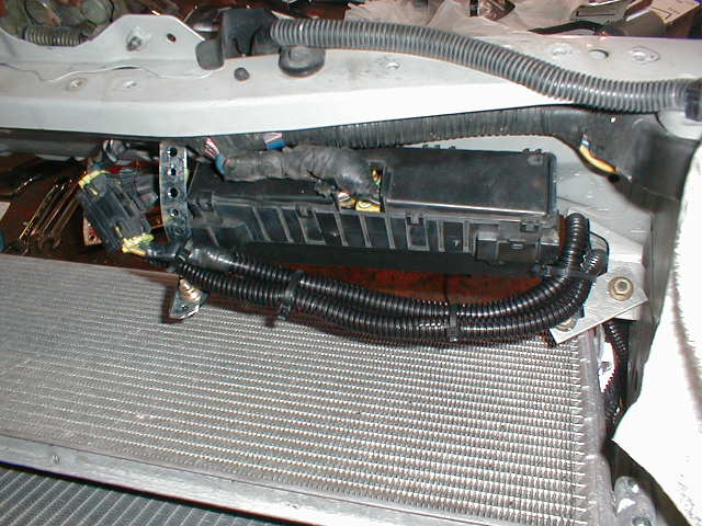
3. Radiator brackets mounting: You have to drill a hole on the toe hook to install the lower radiator brackets. The hole should be about 1.5-1.75" away and 1/4" down from the hole that's used to mount the oil cooler underpanel and in 1/4" in diameter. Replace the plastic rivet that's used to secure the oil cooler underpanel with the 1/4" nuts and bolts included with the V mount. Use the shorter bracket for the passenger side and the longer bracket for the driver side. Use the 1/4" nuts and bolts to bolt on the lower radiator brackets. Do not tighten the brackets fully yet.
 |
 |
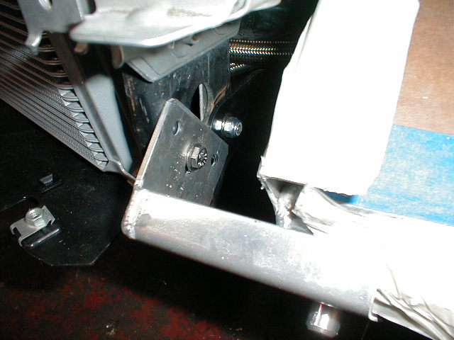 |
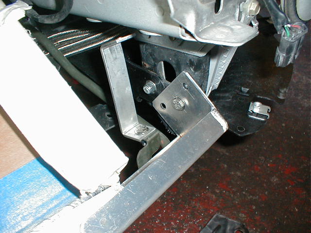
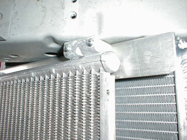
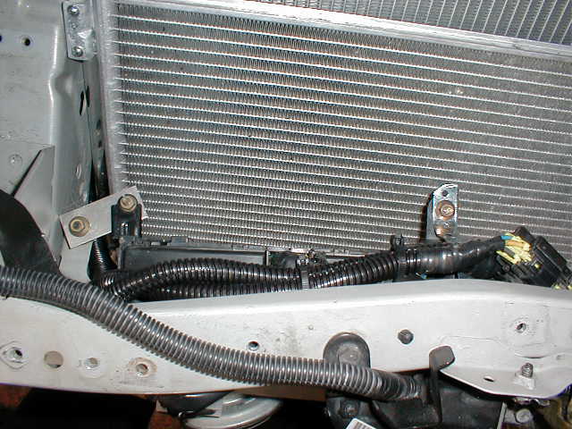
4. Mount the radiator into the lower radiator brackets using the long M6 bolt with 3-4 spacers between the radiator and the bracket. Mark a hole where the upper right radiator bracket should be bolted on. Mark where the slot should be cut out on the cross member for the radiator hose hose to clear. Take out the radiator. Drill a 1/4 hole where the upper right radiator bracket should be bolted on. Cut out the slot for the cross member. Mount the radiator into the lower radiator brackets. Bolt on the upper right radiator bracket with the 1/4" nuts and bolts but do not tighten fully yet.
 |
|
 |
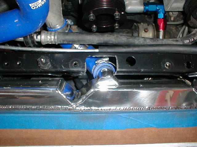 |
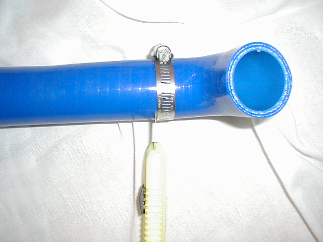
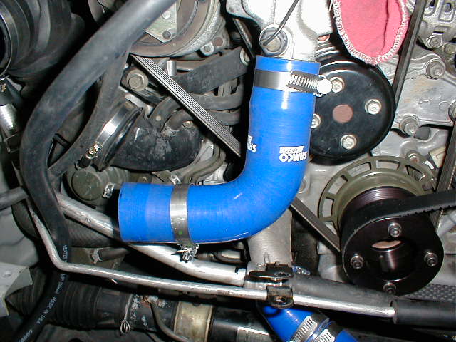
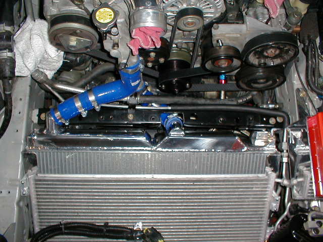
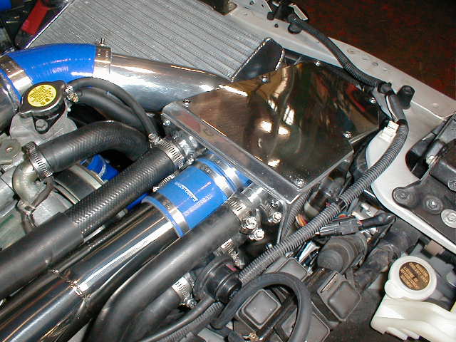
5. Top radiator hose mounting: Bolt on the L shape one first. Measure how much an extension hose you need and cut a section from the 1.5" OD straight radiator hose provided. Use the 1.5" OD hose coupler provided to joint the two together. To make a clean cut on the radiator hose, use the hose clamp as a guide. Clamp it onto the radiator hose where the cut should be made and cut it with a utility knife against the edge of the clamp.
|
|
 |
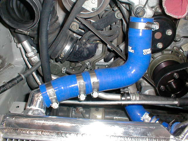 |
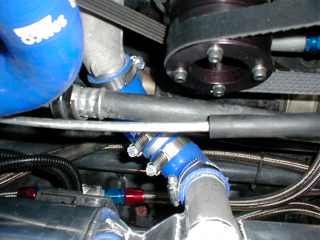
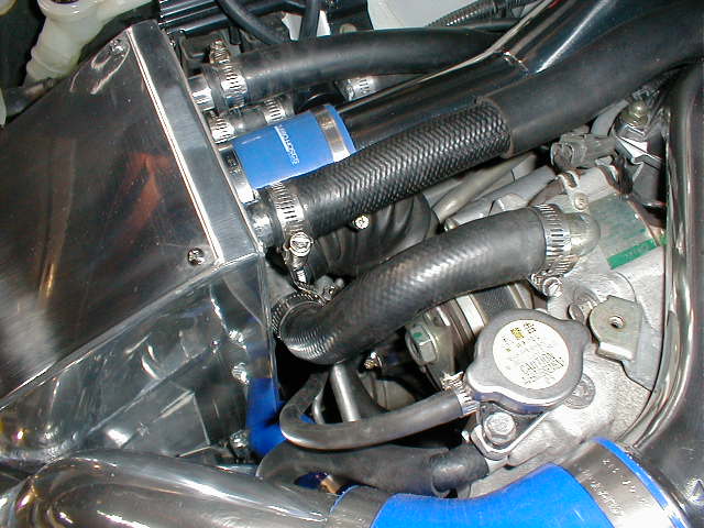
6. Lower radiator hose mounting: Due to different configurations of the V mount setup, the lower radiator hoses are left longer for you to cut them into the right length. Use the 1.5" OD coupler to joint the two together. When they are jointed together, the gap between the two shouldn't be more than 1/4".
 |
 |
7. Put on the cross member. Tighten all the bolts on the radiator brackets.
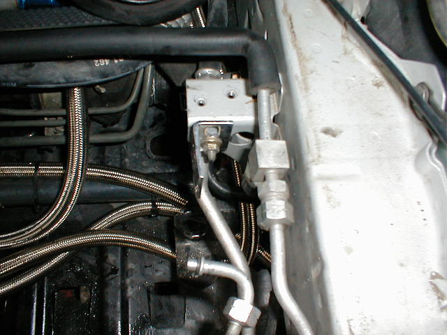
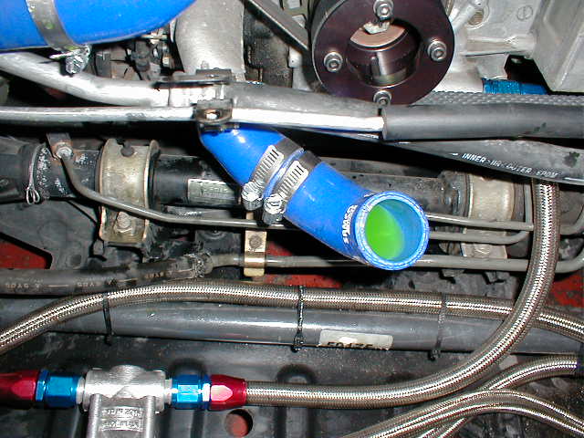
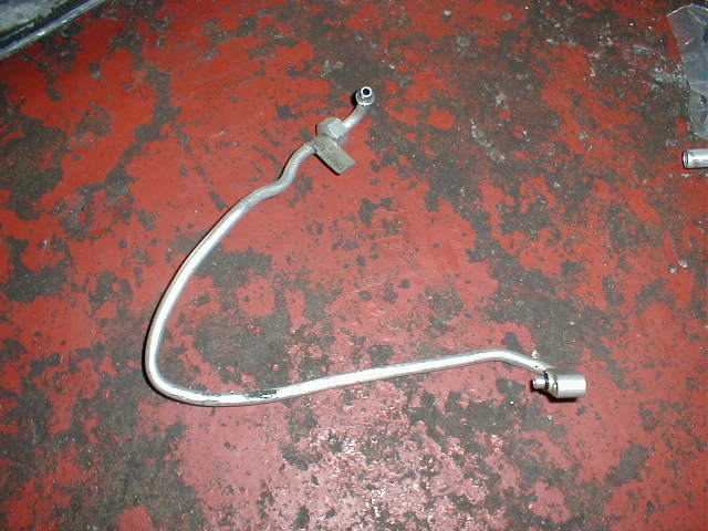
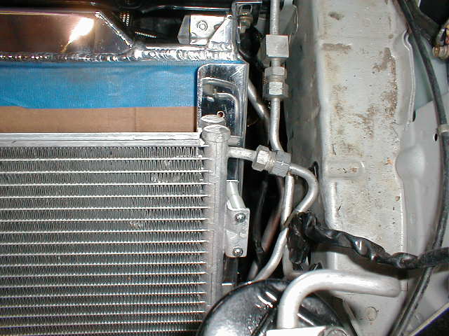
8. A/C line modification: On the A/C dryer, there are two A/C lines. One leads to the fire wall and the other leads to the A/C condenser. You have to bend the one that goes to the A/C condenser to a "V" shape.
 |
 |
 |
 |
 |
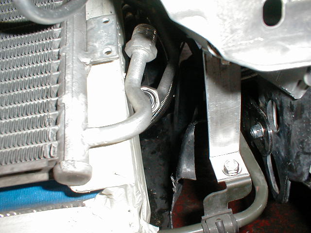
9. A/C condenser modification: The big pipe coming out of the A/C condenser has to be bend down by about 45 degree. The pipe is pretty hard to bend so we recommend you to cut that pipe off, mark the orientation and weld it back onto the A/C condenser. If you mark the orientation and send back the A/C condenser and the fitting, we can weld it back for you for free. First, bolt on the A/C condenser onto the radiator with both pipes facing the driver side, small pipe on top and big pipe at the bottom. The lower left bracket on the A/C condenser has to be cut off first. Screw in the female end of the pipe you just cut off into the pipe coming out of the A/C compressor. Align the section where it's cut. Make marks on both ends. Don't just mark one line across them. Mark at least two lines using permanent marker. Unbolt the condenser and weld the pipe back.
 |
|
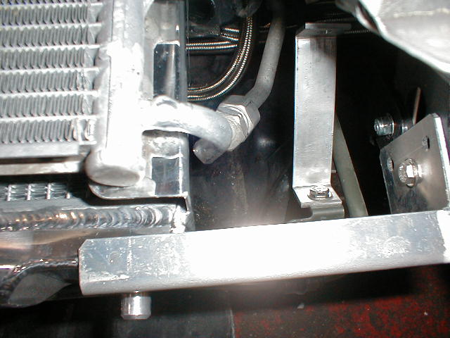 |
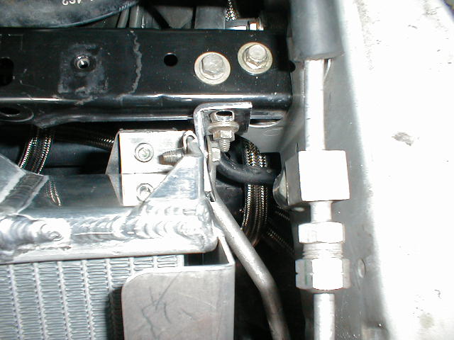
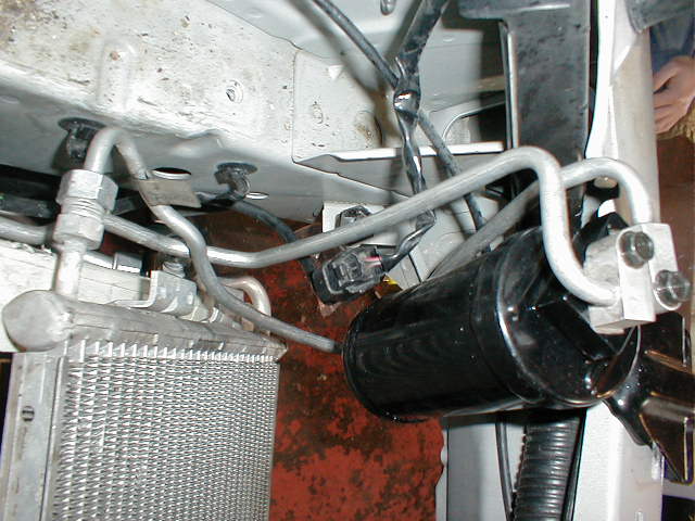
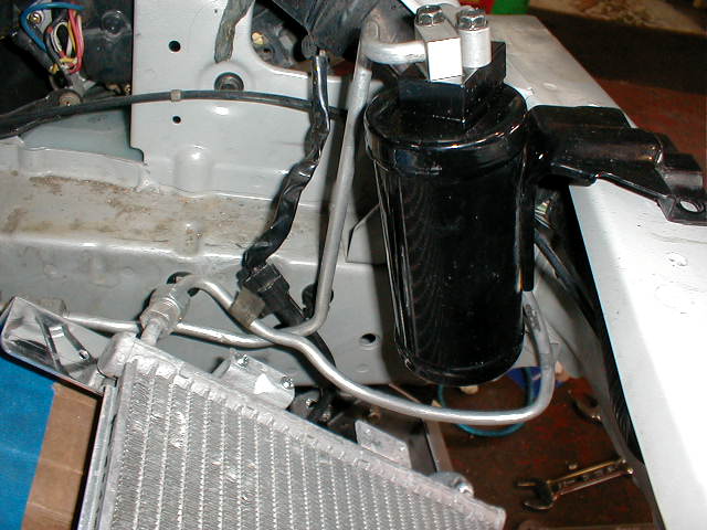
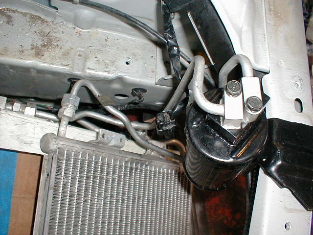
10. A/C condenser installation: Bolt on the "V" shape line onto the A/C condenser first but don't tighten fully yet. There is not going to be enough space between the frame and the A/C for you to screw in the fitting after the A/C condenser is in place so screw it in first and you can tighten later. Use the 1" spacers and 10/32" screws provided and bolt on the A/C condenser. Connect the big A/C lower A/C pipe, the one you cut and reweld.
 |
 |
|
 |
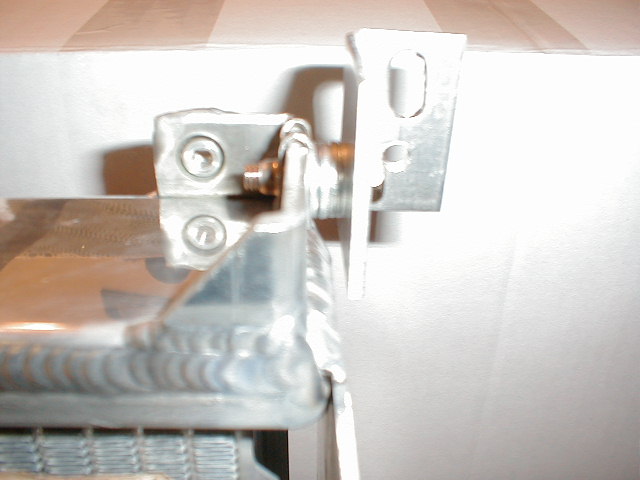
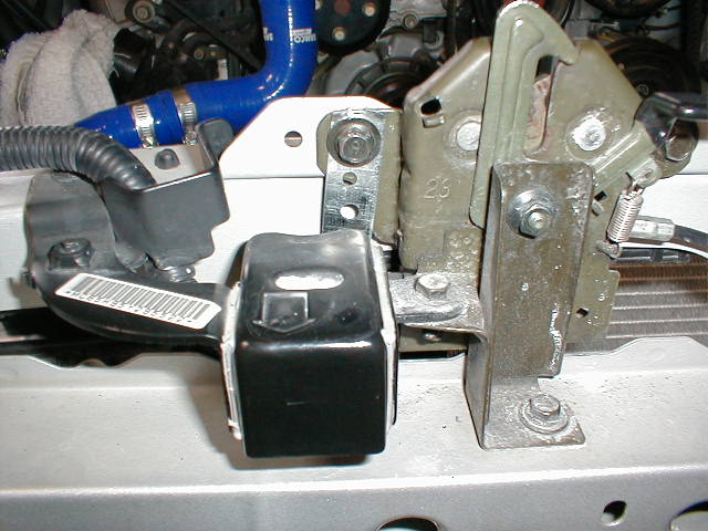
11. Relay Box relocation: Use the bracket and metal strip provided to mount the relay box upside down. Bolt the bracket onto stock radiator mounting point. It's a stud with a rubber base. Run the metal strip below and around the wire loom. Bolt the other end onto the latch catch mounting bolt. If you have not connect the fan connectors, connect them now and zip tie them securely.
 |
 |
 |
 |
 |
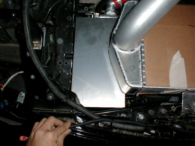
12. V mount shields installation: Slides the shields into place. Depending on the intake you have, you will have different kinds of shields but they will look something like the following:
 |
 |
 |
 |
 |
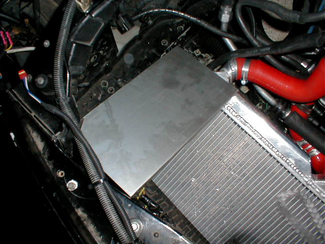 |
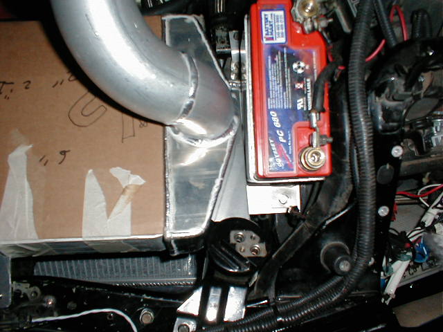
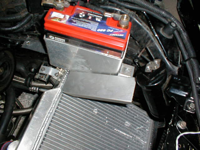
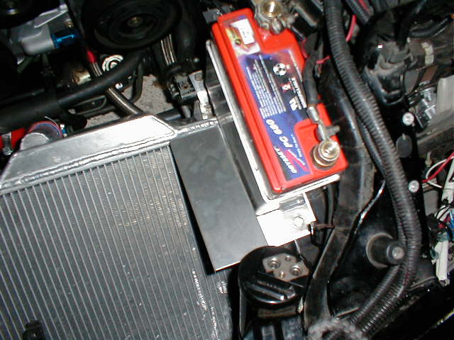
The holes on the shields are not drilled. You will have to drill them yourself. To do so, mount the IC in place. Mark where the holes should be drilled on the shields using a fine point permanent marker. Drill the holes on the shields. For the driver side shield is also another mounting point on the chassis where you mount the mini battery. If you purchase a mini battery with the kit, use the mini battery box to mark the hole. The driver side shield will slide under the battery box. If you are keeping the A/C, the driver side shield will be the shorter version to clear the A/C dryer. It will be too short for the center shield to bolt onto. Bolt the aluminum strip extension provided onto the lower intercooler mounting bracket and bolt the center shield onto the bracket. The intercooler lower brackets for the shields has 4 holes per side. Use the two holes closer to the engine to bolt onto the driver side shield. Use the front two holes to bolt on the extension piece and bolt the driver side flange of the center shield onto the extension piece. After all the holes are marked and drilled, take the shields and intercooler out of the engine bay and bolt the shields onto the intercooler first using the shorter 10/32" screws and lock nuts provided.
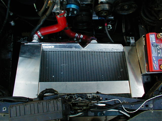
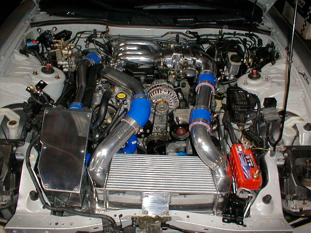
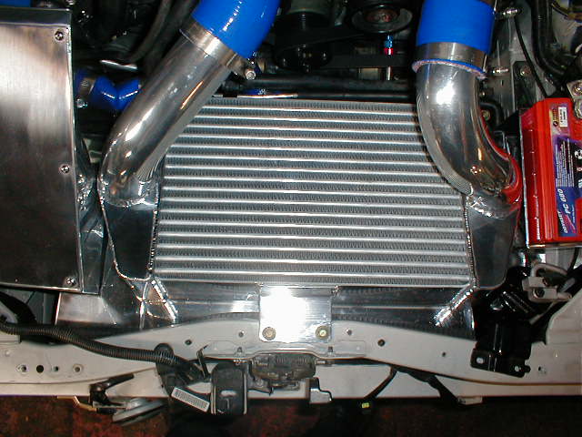
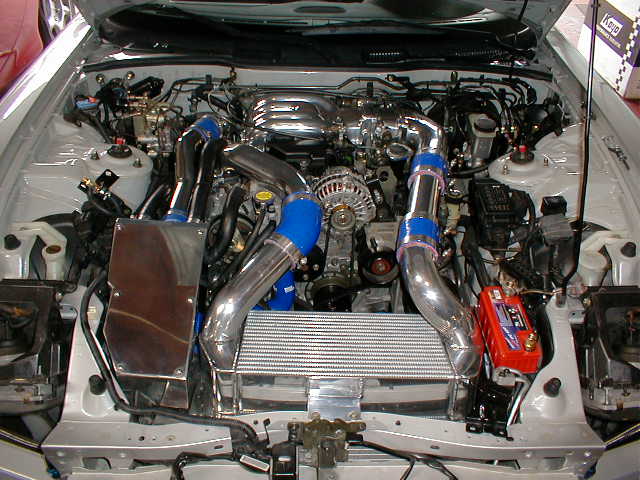
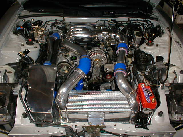
13. Bolt on the intercooler, Greddy elbow, and the connector pipe. The T-bolt clamps provided are heavy duty. Do not over tighten the clamp. It's going to crush the aluminum pipe.
 |
 |
 |
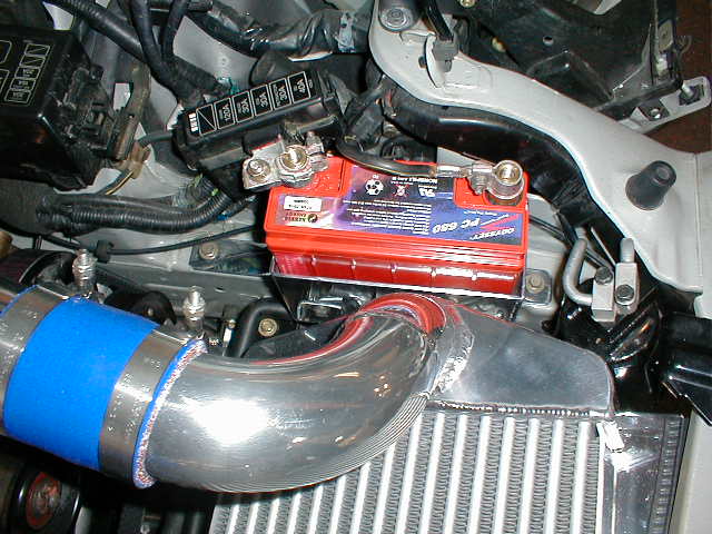
14. If you purchased the mini battery kit, bolt on the mini battery.
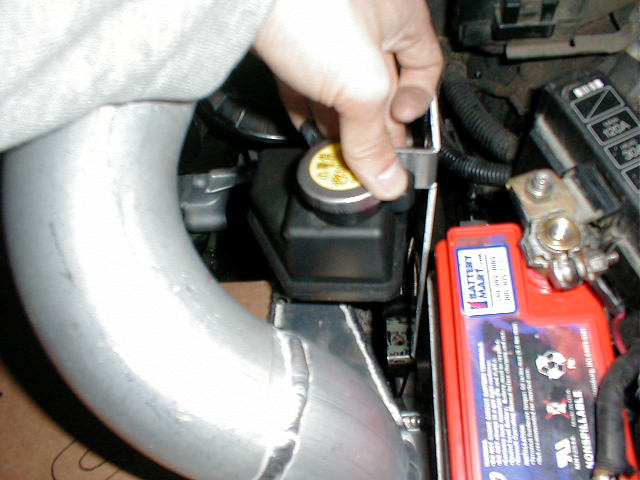
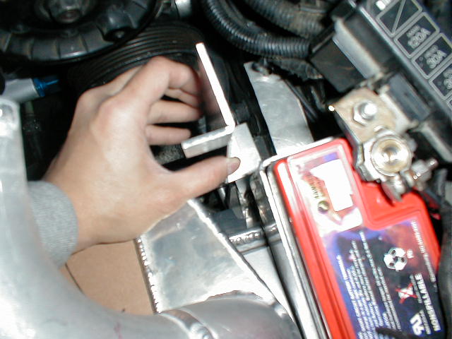
15. If you are keeping the AST, use the bracket provided and bolt it onto the cross member using the existing bolts. The cars we install the V mount on all have the AST eliminated so we have no idea if the stock coolant hoses are long enough. You might have to extend them.
 |
 |
16. If you purchase the V-mount intake with the V mount, install it right now. The flange on the passenger side v mount shield will slide inside the air box. To bolt the air box onto the chassis, you will have to remove the lid first.
 |
 |
 |
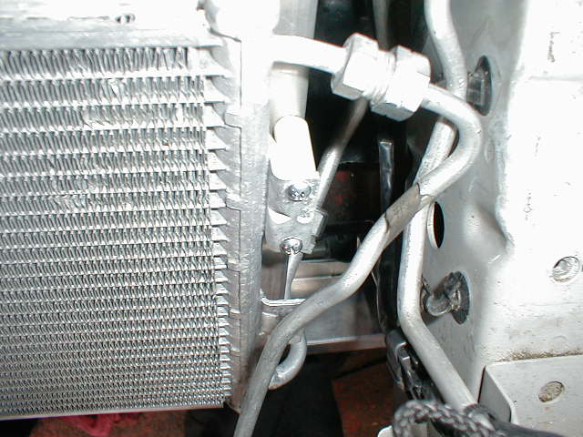
17. Power Steering line: You will have to use the bracket provided to lower the power steering line.
|
|
18. Fill up the coolant. Take off the coolant hose on the throttle body. Keep filling up the coolant until you see coolant coming out of that coolant hose. Put on the radiator cap and then pinch the hose several times to force the trapped air out. Open up the radiator cap and refill it. Repeat the process several times to make sure there is no air bubble inside the cooling system. Put back the coolant hose on the throttle body. Open the AST and fill it up with coolant if you have one. Open the coolant reservoir and fill it up with coolant.
19. Start up the car. Let the car idle and warm up to normal operating temperature and check for coolant leak. Put the A/C fan switch to one and turn on the A/C. Make sure both coolant fans are running.
20. Underpanel modification: You will have to modify the underpanel to fit with the lower radiator bracket. Cut off the section which interferes with the radiator brackets with a dremel cutting wheel.
21. Put back the front bumper
22. Go for a test drive to make sure there is no coolant leak or boost leak. Since the intercooler is a higher flowing unit than the stock one, boost might raise higher than before. Adjust the boost controller if you have one to keep the boost to the safe level. You might have to adjust the fuel map to compensate for the denser air. There might be still some air bubble trapped inside the cooling system. Park your car over night and then check for water level.
If you have any other installation questions, please email rotary_extreme@hotmail.com or call 408-500-6199 between 12pm to 6pm PST. Thank you.
Copyright © 2000-2018 Rotary Extreme. All rights reserved